5. Expansion Boards
5.1. DRV-LV50A-MP1907 Motor Driver Board
Connect J12, J7, J6 to HW, HV, HW
Connect VCC of J10 to 3V3
Connect the three phases of the motor U, V, W and J4
Plug the signal cable of the motor into the J14 socket
Connect 24V power supply to J3
Note
1. **Note the direction of the positive and negative power supply**
2. **Never operate with electricity**
3. **Apply power to the motor driver board and observe whether the current is abnormal**
4. **Make sure the motor driver board is powered down before proceeding to the next step**
Connecting the HPM6750EVK and DRV-LV50A-MP1907
J8 of the HPM6750EVK is connected to J12 of the DRV-LV50A-MP1907。Be careful to check the silkscreen, do not insert the reverse
The figure below shows the overall effect, with red boxes marking the locations of the devices that may need to be operated:

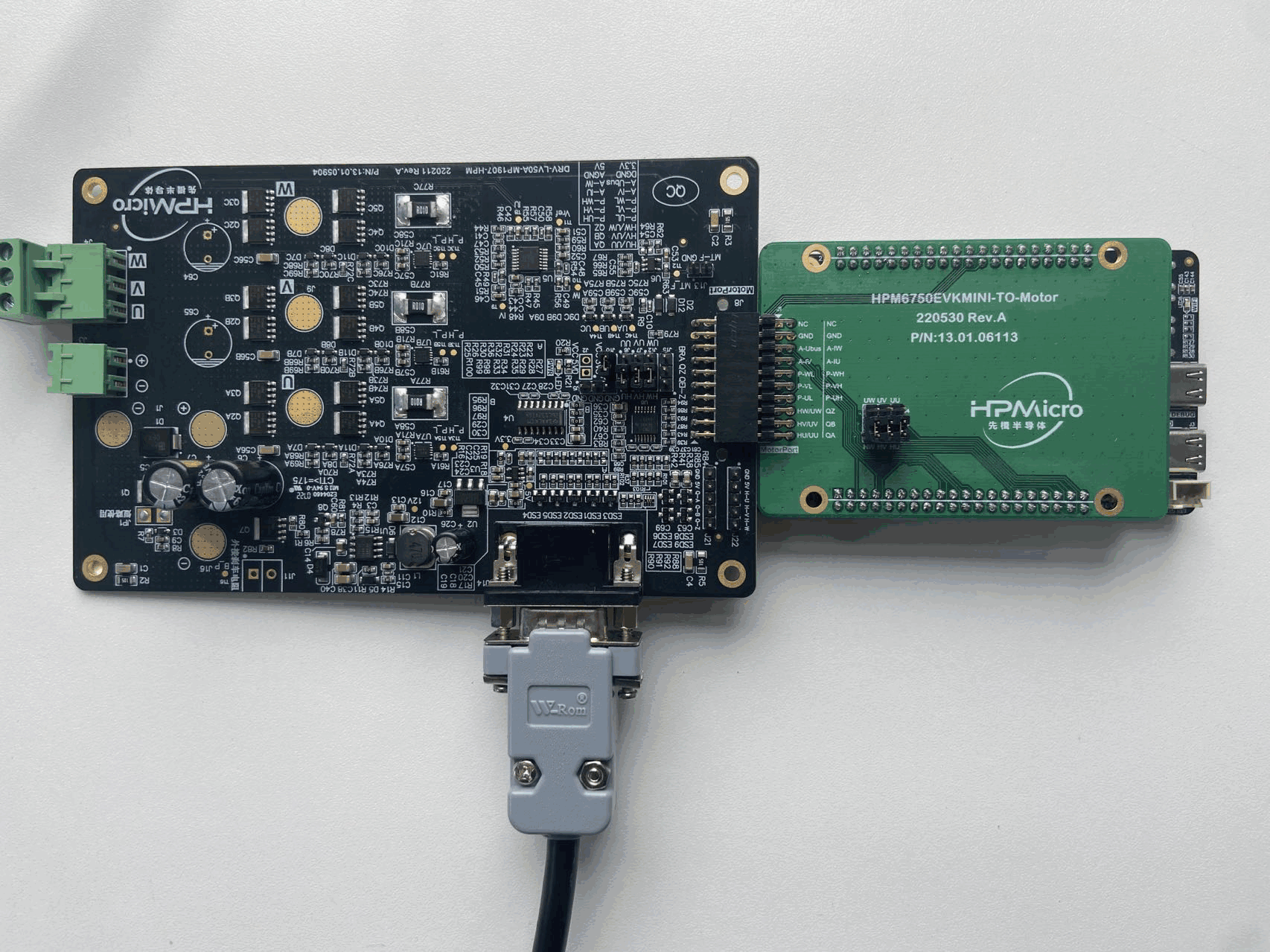
5.2. HPM6750EVKMINI-TO-Motor Motor Expansion Board
To be used withDRV-LV50A-MP1907 Motor Driver Board
Connected with j2 and j3 plug-ins
The HPM6750EVKMINI-TO-Motor motor expansion board, HPM6750EVKMINI board and DRV-LV50A-MP1907 motor driver board are connected as follows:
5.3. LCD-800480W070TC Display
Seven-inch screen, 480*800 resolution
Touch operation support, GT911 5-Point Capacitive Touch Controller