1. HPM6750EVK
1.1. Overview
The HPM6750 is a dual-core flashless MCU running 816Mhz. It has a 2MB continuous on-chip ram. Also, it provides various memory interfaces, including SDRAM, Quad SPI NOR Flash, SD/eMMC. It integrates rich audio and video interfaces, including LCD, pixel DMA, camera, and I2S audio interfaces.
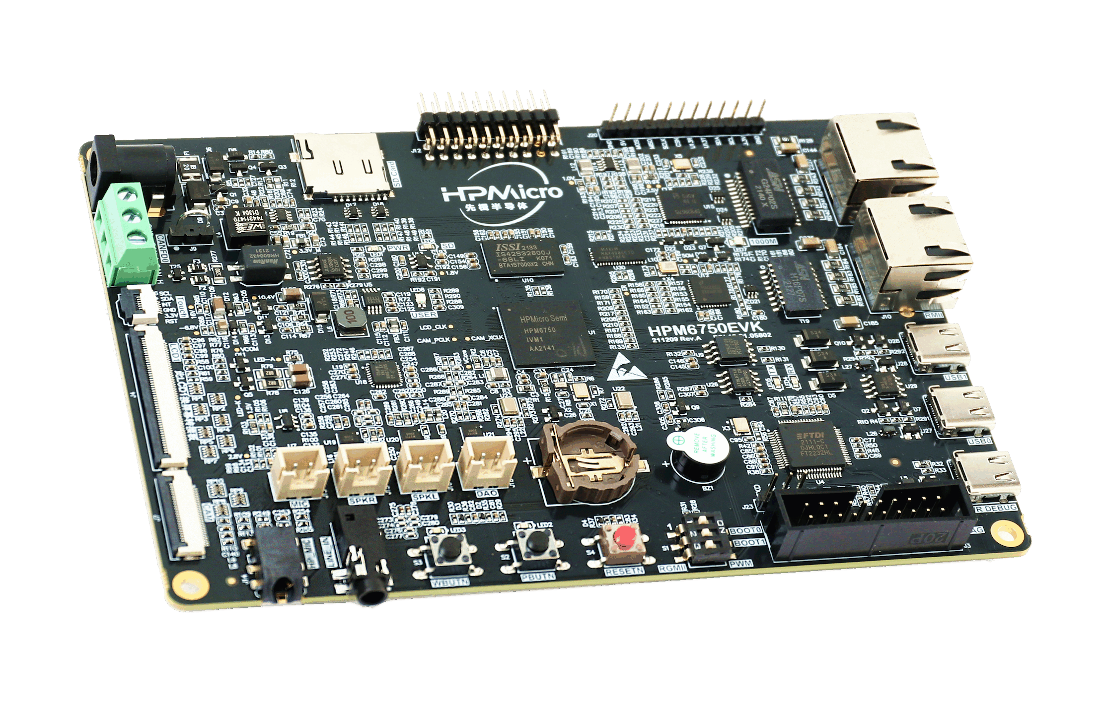
1.2. Hardware
HPM6750IVM MCU (816Mhz, 2MB OCRAM)
Onboard Memory
256Mb SDRAM
128Mb Quad SPI NOR Flash
Display & Camera
LCD connector
Camera (DVP)
Ethernet
1000 Mbits PHY
100 Mbits PHY
USB
USB type C (USB 2.0 OTG) connector x3
Audio
Line in
Mic
Speaker
DAO
Others
TF Slot
FT2232
Beeper
RGB LED
CAN
Expansion port
Motor control
1.3. DIP Switch S1
Bit 2 and 3 controls boot mode
bit[2:3] |
Description |
|---|---|
OFF, OFF |
Boot from Quad SPI NOR flash |
OFF, ON |
Serial boot |
ON, OFF |
ISP |
Change the position of bit 1 to select between PWM and Gigabit Ethernet
Bit1 |
Description |
|---|---|
OFF |
Gigabit Ethernet |
ON |
PWM |
1.5. Pin Description
PWM Pin:
Function |
Position |
|---|---|
PWM2.P0 |
J12[14] |
PWM2.P1 |
J12[13] |
|
SPI Pin:
Function |
Position |
|---|---|
SPI2.CSN |
J20[7] |
SPI2.SCLK |
J20[8] |
SPI2.MISO |
J20[9] |
SPI2.MOSI |
J20[10] |
I2C Pin:
Function |
Position |
|---|---|
I2C0.SCL |
J20[3] |
I2C0.SDA |
J20[4] |
UART for core1 debug console
Function |
Position |
|---|---|
UART13.TXD |
J20[5] |
UART13.RXD |
J20[6] |
ACMP Pin
Function |
Position |
|---|---|
CMP.INN6 |
J12[8] |
CMP.COMP_1 |
J12[6] |
GPTMR Pin
Function |
Position |
|---|---|
GPTMR4.CAPT_1 |
J12[6] |
GPTMR3.COMP_1 |
J12[7] |
ADC12 Pin
Function |
Position |
|---|---|
ADC0/1/2.VINP11 |
J12[6] |
ADC0/1/2.VINP10 |
J12[7] |
ADC0/1/2.VINP7 |
J12[8] |
ADC16 Pin
Function |
Position |
|---|---|
ADC3.INA2 |
J12[5] |
headphone interface
Function |
Position |
|---|---|
3.5mm headphone |
J14 |
audio input interface
Function |
Position |
|---|---|
3.5mm LIN_IN |
J17 |
DAO interface
Function |
Position |
|---|---|
Speaker |
J18 |